Kind
What kind of capacitors are there?
The following table shows the kind of capacitors intended for general consumer electronics.
| Kind | Feature | Fit for |
|---|---|---|
| Aluminum Electrolytic Capacitor | Aluminum electrolytic capacitors have large capacitance, and theirESR, ESL frequency characteristics are not good. Therefore, they are not suitable for power lines near IC and decoupling. As they have polarity, reverse voltage and overvoltage cause leakage of liquids and/or explosion. You should mind for that in using them. | voltage smoothing in power lines, power backup |
| Tantalum Electrolytic Capacitor | Features of tantalum electrolytic capacitors are like aluminum electrolytic capacitors. Different points are that they are smaller than and superior in ESR, ESL frequency characteristics to aluminum capacitors. However, their ESR, ESL characteristics do not reach ceramic capacitors. As they also have polarity, reverse voltage and overvoltage cause fuming and/or heating. | voltage smoothing in power lines, bypass |
| Film Capacitor | Film Capacitors have low capacitance. Theircapacitance does not change by environmental factors such as temperature, voltage and so on. They always keep constant characteristics. | analog circuit |
| Multilayer Ceramic Capacitor | capacitance range of multilayer ceramic capacitors spreads roughly from 0.5pF to 100uF. They have good ESR, ESL frequency characteristics enough to pass analog signals without any distortion by selecting correct capacitance. Capacitors classified to high dielectric type have largecapacitance and their capacitance depend largely on voltage and temperature. It is important to take this into account when dealing with the circuit that requires the correct capacitance. As multilayer ceramic capacitors are inexpensive and small, large quantities can be mounted even in a small equipment. | analog, digital, power circuit |
What kind of ceramic capacitors are there?
There are various kind of ceramic capacitors. We are introducing following ceramic capacitors in our catalog.
| Product Name | Capacitance Range | Description |
|---|---|---|
| Multilayer Ceramic Capacitors (High dielectric type) |
100pF~470uF | These products are intended
mainly for power lines. They are best fit for backup and voltage smoothing. |
| Multilayer Ceramic Capacitors (Temperature compensating type) |
0.2pF~1000pF | Capacitance change by temperature and voltage are very small in these products. They are best fit for circuits that require fixed capacitance such as filters. |
| Multilayer Ceramic Capacitors for High Frequency Applications | 0.2pF~22pF | Since these products have low capacitance and high self-resonant frequency, they are fit for use in high frequency range. They also have low electrical loss, therefore, they are best fit for matching circuit, etc. |
| Super Low Distortion Multilayer Ceramic Capacitors | 390pF~0.1uF | These products are superior in electrical and mechanical strength and have high heat resistance. Therefore, shock noise and electrical distortion caused by them are small. They are fit for PLL and oscilator circuit, etc. |
| Low Distortion High Value Multilayer Ceramic
Capacitors (CF_LD) |
0.22uF~10uF | These products have both low electrical distortion and high capacitance. They are effective for preventing self-ringing. |
| Medium-High Voltage Multilayer Ceramic Capacitors | 8pF~4.7uF | These products have high rated voltage. They are intended for high voltage lines. |
| LW Reversal Decoupling Capacitors
(LWDC™) |
0.1uF~22uF | Since these products have low ESR and ESL, they are superior in canceling ripple current and high frequency noise. They are best fit for decoupling, etc. They also have enough capacitance to be used for voltage smoothing circuit. |
| MLCC (High dielectric type) for Automotive (BODY & CHASSIS, INFOTAINMENT) Applications | 220pF~47uF | These products have higher reliability than products for general electronic equipment. They have enough reliability to be used for automotive electronic equipments for body and chassis, car infotainment system. |
| MLCC (Temperature compensating type) for Automotive (BODY & CHASSIS, INFOTAINMENT) Applications | 0.2pF~1000pF | |
| Medium-High Voltage MLCC for Automotive (BODY & CHASSIS, INFOTAINMENT) Applications | 220pF~4.7uF | |
| LW Reversal Decoupling Capacitors for Automotive (BODY & CHASSIS, INFOTAINMENT) Applications (LWDC™) | 0.1uF~22uF | |
| High Frequency Medium-High Voltage MLCC for Automotive (BODY & CHASSIS, INFOTAINMENT) Applications | 0.2pF~100pF | Q value in the high frequency range is superior compared to other types of multilayer capacitors. Small case sizes with high rated voltage. |
| Soft Termination MLCC for Automotive (BODY & CHASSIS, INFOTAINMENT) Applications | 1000pF~47uF | These products are intended for suppressing the crack by using conductive resin at external terminal to absorb the vibration, stress and thermal shock from the substrate. |
| MLCC for Automotive (POWERTRAIN, SAFETY) Applications | 1000pF~10uF | These products are intended for automotive electronic equipments for powertrain, safety system where high reliability is strongly required. |
| MLCC (High dielectric type) for
Telecommunications infrastructure and Industrial equipment / Medical
devices (high dielectric type) |
220pF~220uF | These products have higher reliability than products for general electronic equipment. They have enough reliability to be used for telecommunications infrastructure, industrial equipment and medical devices. |
| MLCC (Temperature compensating type) for Telecommunications infrastructure and Industrial equipment / Medical devices | 0.2pF~1000pF | |
| Medium-High Voltage MLCC for Telecommunications infrastructure and Industrial equipment / Medical devices | 220pF~4.7uF | |
| LW Reversal Decoupling Capacitors for Telecommunications infrastructure and Industrial equipment / Medical devices (LWDC™) | 0.1uF~22uF | |
| High Frequency Medium-High Voltage MLCC for Telecommunications infrastructure and Industrial equipment / Medical devices | 0.2pF~100pF | |
| Soft Termination MLCC for Telecommunications infrastructure and Industrial equipment / Medical devices | 1000pF~47uF |
-
*Capacitance range is as of November 2019.
You can find features and applications of these products in TY-COMPAS, a web application for searching and displaying specifications and characteristics of our products. Please use it for finding information of our products. The list of each product is summarized in our catalogs. Please read them as an another kind of information source.
Please contact your sales office for products not included in catalogs.
Please introduce the product lineup of ceramic capacitors.
Our ceramic capacitor product lineup can be found at TY-COMPAS.
Please tell me how to read Part Number.
The meaning of Part Number is summarized in catalogs. Please click following links of your concerning products.
Multilayer Ceramic Capacitors
- General Electronic Equipment for Consumer
- Automotive Electronic Equipment(POWERTRAIN, SAFETY)
- Automotive Electronic Equipment (BODY & CHASSIS, INFOTAINMENT)
- Telecommunications Infrastructure and Industrial Equipment
- Medical Devices classified as GHTF Classes A or B (Japan Classes Ⅰ or Ⅱ)
- Medical Devices classified as GHTF Class C (Japan Class Ⅲ)
-
*A catalog download page for each product is here.
Characteristics
What is capacitance of capacitor?
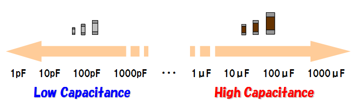
Capacitance is a physical quantity that describes the ability of electrial storage in capacitors. F(Farad) is an unit for expressing capacitance.
A quantity expressed by F is too large for capacitance range where ceramic capacitors are generally used. Instead, μF(micro Farad, one millionth of Farad) and pF(pico Farad, one trillionth of Farad) are often used as capacitance units of ceramic capacitors. We can roughly devide ceramic capacitors more than 1μF to high capacitance, and ones less than 1000pF to low capacitance category. However, the criteria of devision depend on situations.
What are impedance frequency characteristics in capacitors?
What is ESR/ESL of capacitors?
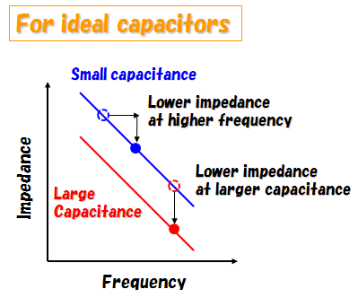
Impedance of capacitors depends on capacitance and frequency. In an ideal capacitor, impedance becomes lower as capacitance is larger. Also, the impedance becomes lower as the frequency is higher.
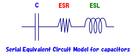
Actually, the capacitor has resistance and inductance. In a simple expression, those characteristics can be written as a C, R, L serial equivalent circuit model. This R is called "Equivalent Series Resistance(ESR)", and L is called "Equivalent Series Inductance(ESL)".
Different from an ideal capacitor, the impedance of actual capcitor changes its tendency at a certain frequency because of ESL. This frequency is called "Self Resonant Frequency(SRF)". In higher frequency range than SRF, the impedance becomes larger by increasing frequency because ESL affects to impedance. At SRF, capacitance and ESL mutually erase each impedance. Therefore, only impedance by ESR remains at SRF.
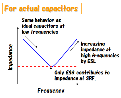
Thus, the impedance of capcitor depends on frequency. That is impedance frequency characteristics in capacitors.
ESR and ESL both cause reduction of performance. Generally speaking, capacitors with lower ESR and ESL work better than higher ones. If ESR of a capacitor is large, it may cause generation of heat and voltage drop when the IC is operating. If ESL of a capacitor is large, it may cause ringing of waveform. ESR and ESL also varies depending on frequency in actual capacitors. Therefore, it is important to know ESR and ESL value at frequency in your concern. See also this document for more detail.
Multilayer ceramic capacitors are generally superior in ESR and ESL characteristics to other kind of capacitors. We can provide LW Reversal Decoupling Capacitors (LWDC™) that have even more lower ESR and ESL than general ceramic capacitors. Please try them in your application.
Does capacitance of ceramic capacitors change by
voltage?
What are capacitance voltage/bias characteristics in capacitors?
In high dielectric
type capacitors, capacitance
changes by applying voltage to them. Capacitance change by applied voltage is called capacitance voltage characteristics or
bias characteristics.
This is caused by the material used in ceramic
capacitors, and generally occurs on ceramic capacitors of other companies.
In
temperature compensating type
capacitors such as Multilayer Ceramic Capacitors(Temperature compensating type)
and Multilayer Ceramic Capacitors for High Frequency Applications (1GHz+),
almost no capacitance change by voltage
occurs due to the difference of the material from high dielectric type.
The following picture is showing capacitance change ratio by applying DC voltage to our product LMK212BJ105KD-T.
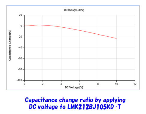
In both cases, it is important to select an adequate
capacitor refering to voltage characteristics so as to get required capacitance at applied voltage in actual
circuits.
Please access to TY-COMPAS for voltage characteristics of each product
where you can search specifications and characteristics of our products.
Does capacitance of ceramic capacitors change by
temperature?
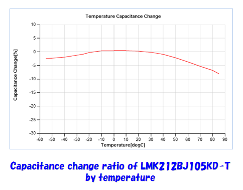
What are capacitance temperature characteristics in capacitors?
Capacitance of ceramic capacitors changes by ambient temperature. This change is called capacitance temperature characteristics.This is caused by the material used in ceramic capacitors, and generally occurs on ceramic capacitors of other companies.
The following picture is showing capacitance change ratio of our product LMK212BJ105KD-T by temperature.
About temperature characteristics of ceramic capacitors, there are two standards widely used. One is Japanese Industrial Standards(JIS), and the other is the standard by Electronic Industries Alliance(EIA). Ceramic capacitor manufacturers including our company provide temperature characteristic symbol of both/either JIS and/or EIA to each product. From this information, You can know the operating temperature range and coefficient of capacitance within the operating temperature range or capacitance change ratio belonging to each product. The following table is showing representative JIS and EIA temperature characteristic symbol list, and the list is also showing corresponding operating temperature range, temperature coefficient and capacitance change ratio.
CLASS1(Temperature compensating type)
| Symbol | Operating
temperature range [℃] |
Temperature
coefficient [ppm/℃] |
|
|---|---|---|---|
| JIS | EIA | ||
| CG | C0G | -55 to +125 | 0±30 |
| CH | C0H | 0±60 | |
| CJ | C0J | 0±120 | |
| CK | C0K | 0±250 | |
| UJ | U2J | -750±120 | |
| UK | U2K | -750±250 | |
| SL | – | -1000 to +350 | |
CLASS2(high dielectric type)
| Symbol | Operating
temperature range [℃] |
Capacitance
change ratio [%] |
|
|---|---|---|---|
| JIS | EIA | ||
| B | – | -25 to +85 | ±10 |
| – | X5R | -55 to +85 | ±15 |
| – | X6S | -55 to +105 | ±22 |
| – | X7R | -55 to +125 | ±15 |
| – | X7S | -55 to +125 | ±22 |
| – | X7T | -55 to +125 | +22/-33 |
| F | – | -25 to +85 | +30/-80 |
| – | Y5V | -30 to +85 | +22/-82 |
-
*Reference temperature is 20℃ in JIS and 25℃ in EIA.
Temperature coefficient and capacitance change ratio can be calculated from capacitance CT at operating temperature T and capacitanceCT0 at reference temperature T0 using following formulas. These values must be within the range shown in the above table.
![温度係数=Ст-Сто/Сто(T-To)×10⁶ [ppm/°C]](/en/product/support/useful/faq/mlcc/images/faq_q009_02.png)
![capacitance変化率=Ст-Сто/Сто×100 [%]](/en/product/support/useful/faq/mlcc/images/faq_q009_03.png)
Please refer to TY-COMPAS for each product where you can search specifications and characteristics of our products.
Why do capacitors generate heat?
Capacitors have resistance in their electrodes and dielectrics. This resistance generates heat when AC current like ripple current passes through capacitors. It is very important to select capasitors with low ESR not to generate heat. Ceramic capacitors have lower ESR among capacitors and are best fit for preventing heat. You can find ESR characteristics of our ceramic capacitors in TY-COMPAS.
How can I get the characteristic data of ceramic capacitors?
We are serving you TY-COMPAS. You can search each product, display specifications and characteristic charts on your browser by this web application. Please make most of it!
Does ESR/ESL of ceramic capacitor change by the number of capacitor layers?
Yes. A section of multilayer ceramic capacitors is as a picture shown below. Changing it to an equivalent circuit, resistance and inductance of internal electrodes are connected in parallel.
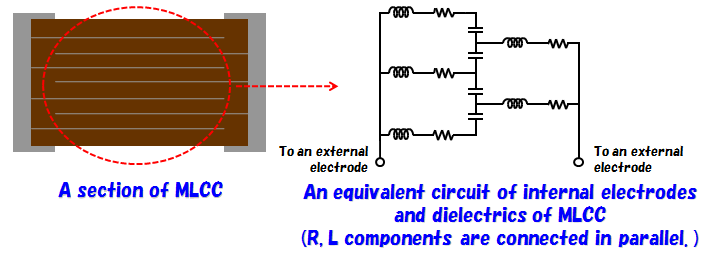
Therefore, as the number of layers increase, the number of resistance and inductance connected in parallel also increase. This results in reduction of ESR and ESL.
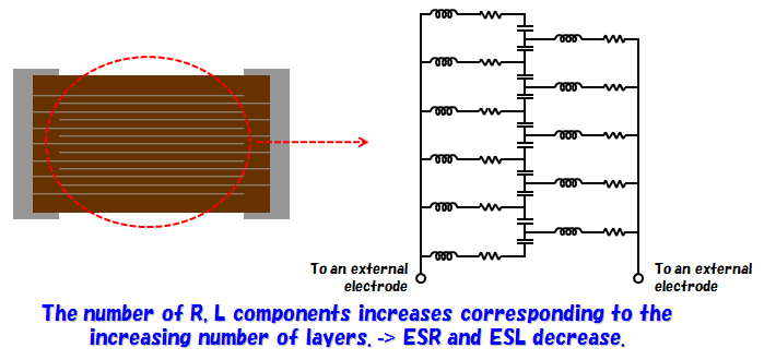
Generally, as the size of a component is larger, the length of the internal electrodes becomes longer. Thus the resistance and inductance per an internal electrode become larger. In case that the size of a component is large, its ESR and/or ESL may be higher than the one with small size and a few of layers though the number of its layers is many.
Circuit
How do ceramic capacitors work on the circuit?
Main tasks of ceramic capacitors on the circuit are coupling, decoupling, smoothing and filtering.
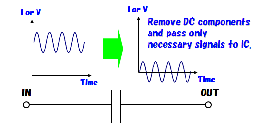
- 1.Coupling
-
In this process, ceramic capacitors remove DC components and pass only AC components.
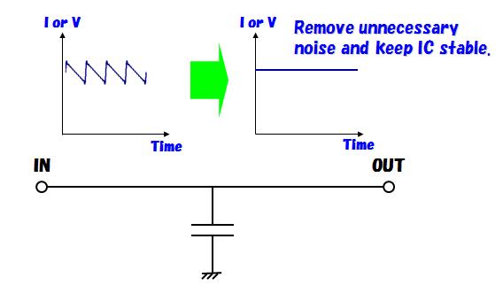
- 2.Decoupling
-
In this process, ceramic capacitors remove unnecessary noise components.
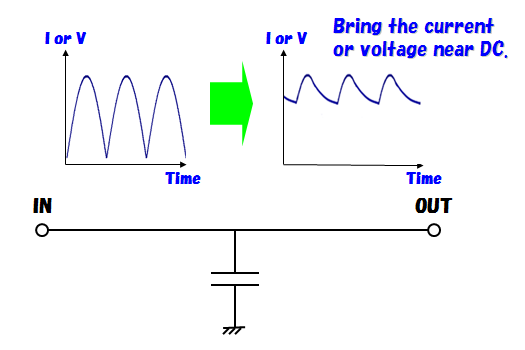
- 3.Smoothing
-
In this process, ceramic capacitors smooth voltage after rectifying and make voltage nearer to DC.
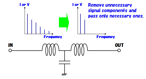
- 4.Filtering
-
In this process, ceramic capacitors corporated with coils and resistors remove signals in unnecessary frequency bands and pass only signals in necessary frequency bands.
What is ripple current?
The ripple current in capacitors mainly means the current flowing into capacitors when the load current to IC changes.
At this time, capacitors generate heat by the ripple current since they have resistance called ESR in themselves. In aluminum capacitors etc., the current value when temperature rises to a certain degree (different among manufacturers) by capacitor heat is specified as maximum current value able to flow into capacitors. This is called permissible ripple current.
Though there is no specification for the permissible ripple current in ceramic capacitors, they tend to generate lower heat than aluminum capacitors etc. because ESR characteristics of ceramic capacitors are better than that of aluminum capacitors. Please make sure to use our products so that the sum of ambient temperature and temperature rise by self-heating is within the operating temperature range.
Please refer to temperature rise characteristics by self-heating of each product in TY-COMPAS.
Please tell me how to use ceramic capacitors on the actual circuit.
You can get the technical information about capacitors from "The Fundamental Technical Knowledge of Passive Components" on our home page. The capacitor operation on the actual circuit is explained in this document. Please access to this.
Why cannot I get the same value as nominal capacitance when I use ceramic capacitors on the actual circuit?
Capacitance of ceramic capacitors changes by temperature, voltage, frequency, aging and so on. Nominal capacitance is measured under conditions described in the catalog, and does not always correspond to capacitance in the actual operating environment. About our products, you can confirm the capacitancechange by temperature, voltage and frequency in TY-COMPAS.
Can I connect ceramic capacitors in series?
Yes. However, it is considered that the concentrated voltage can be applied to one or more capacitors of all by the unevenness of capacitance and/or capacitance change by voltage and temperature etc. Please make sure that the rated voltage of each capacitor exceeds the operating line voltage.
Measurement
How can I measure capacitance of ceramic capacitors?
Capacitanceof ceramic capacitors is measured using measurement instruments such as a LCR meter (measurement principle is see below.) and an impedance analyzer.
In our company, the nominal capacitance of ceramic capacitors is measured under
following conditions.
(Measurement conditions are also described on the reliability data page in the catalog. Catalogs are here.)
| Class 1 | Class 2 | |||
|---|---|---|---|---|
| Standard | High Frequency Type | C ≤ 10uF | C > 10uF | |
| Preconditioning | None | Thermal treatment (at 150℃ for 1hr) (*2) | ||
| Measuring frequency | 1MHz±10% | 1kHz±10% | 120±10Hz | |
| Measuring voltage (*1) | 0.5 ~ 5Vrms | 1±0.2Vrms | 0.5±0.1Vrms | |
| Bias application | None | |||
-
*1The figures indicate typical specifications. Please refer to individual specifications in detail.
-
*2Thermal treatment : Initial value shall be measured after test sample is heat-treated at 150+0/-10℃ for an hour and kept at room temperature for 24±2hours.
Note that capacitance changes by frequency, temperature, voltage and so on.
Please refer to individual specifications about measurement instruments and conditions of each product. Please refer to this page about measurement instruments and conditions used to get characteristics on data sheet.
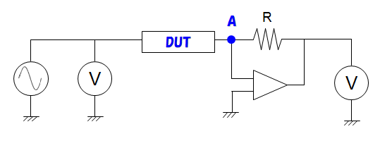
LCR meter (measurement principle)
The measurement method called "auto balancing bridge method" shown as the figure below is adopted to LCR meters by a lot of manufacturers of measurement instruments. In this method, the current at a measured object(=DUT) and a known resistance R is automatically adjusted to be same, that is the voltage at point A becomes 0. Then, LCR meter calculates complex impedance from the voltage applied to a DUT and a known resistance R. Capacitance of ceramic capaictors is derived from the reactance component of this complex impedance.
Please refer to the manufacturers' web site in details.
Please tell me measurement conditions and instruments used to get characteristic data of ceramic capacitors.
Please refer to following explanations.
| Measurement instruments |
|
|---|---|
| Jigs |
|
| DC power supplies |
|
| Measuring frequency |
|
| Ambient temperature | 25±2℃ |
| Measurement instruments |
|
|---|---|
| Temperature chamber |
|
| Ripple current characteristics |
|
| Multifunction generator |
|
|---|---|
| Bipolar amplifier |
|
| Infrared thermometer |
|
| Measuring frequency |
|
| Ambient temperature |
|
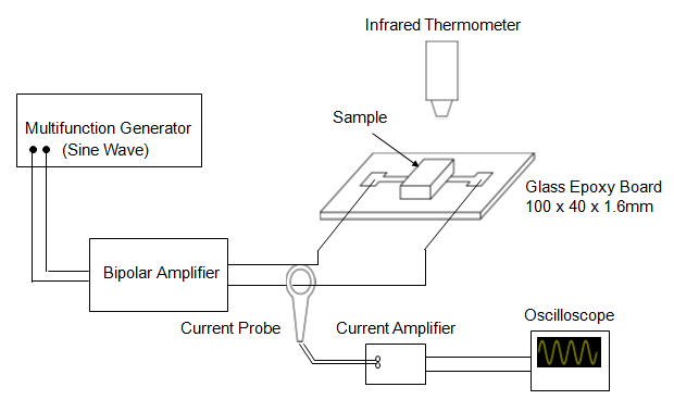
In measurement system above, the current is increased while measuring temperature of the product and the ripple current value at that temperature. That is done until the temperature achieves 20℃ over the initial state. This procedure is repeated for each frequency specified in the table above.
4.Impedance and capacitance frequency characteristics
Please refer to this.
Why is measured capacitance different from nominal capacitance?
Capacitance of ceramic capacitors changes by temperature, voltage, frequency, aging and so on. Nominal capacitance is measured under conditions described in the catalog. If you measure the capacitance under the different condition, the result is not always correspond to nominal capacitance. About our products, you can confirm the capacitance change by temperature, voltage and frequency in TY-COMPAS.
Also, the characteristics of used jigs is contained in the measurement result. Therefore, you must remove the influence of measurement jigs to get accurate capacitance. Please refer to the manufacturer's manual for the method of compensation.
Quality
What are the structure and materials of ceramic capacitors?
For details on the structure and materials of ceramic capacitors, please refer to this section.
What is the manufacturing process for multilayer ceramic capacitors?
For details on the structure and materials of ceramic capacitors, please refer to this section.
What is capacitance aging of ceramic capacitors?
Capacitance of high dielectric type ceramic
capacitors gradually decreases over time. This phenomenon is called aging. Aging
occurs because substances constructing ceramic capacitors gradually change their
structure to be more stable electrically. This is a common phenomenon generally
observed in ceramic capacitors. The reduced capacitance returns to the original value through
thermal treatment.
This is not the case for temperature
compensating type products such as Multilayer Ceramic
Capacitors(Temperature compensating type) and Multilayer Ceramic Capacitors for
High Frequency Applications (1GHz+) because used materials are different from high dielectric type.
What test cases are there in reliability tests of ceramic capacitors?
The following table shows items for reliability tests of ceramic capacitors that our company performs.
| Reliability items | Explanation |
|---|---|
| Operating Temperature Range | Temperature range where the product can be used |
| Storage Conditions | Temperature range where the product can be stored |
| Rated Voltage | Upper voltage limit where the product can be used |
| Withstanding Voltage (Between terminals) | No breakdown or damage when specified over voltage is applied |
| Insulation Resistance | Insulation resistance must not be below the specified value. |
| Capacitance (Tolerance) | Capacitance at room temperature must be within the specified range. |
| Q or Dissipation Factor | Lower Q limit or upper dissipation factor limit at room temperature |
| Temperature Characteristic (Without voltage application) | Capacitance change by temperature must be within specified range at operating temperature range. |
| Deflection | The apperance must be normal and capacitance must be within specified range after specified deflection is given to the board. |
| Adhesive Strength of Terminal Electrodes | No terminal separation or its indication by specified physical pressure |
| Body Strength | No mechanical damage by specified physical pressure |
| Solderability | At least 95% of terminal electrode is covered by new solder. |
| Resistance to Soldering | The apperance must be normal and each electric characteristics must not change over specified range after the product is exposed to high temperature by soldering. |
| Temperature Cycle (Thermal Shock) | The apperance must be normal and each electric characteristics must not change over specified range after the product is alternately exposed to the upper and lower limit of the operating temperature range specified number of times. |
| Humidity (Steady State) | The apperance must be normal and each electric characteristics must not change over specified range after the product is continuously exposed to the highly humid environment for specified time. |
| Humidity Loading | The apperance must be normal and each electric characteristics must not change over specified range after the specified voltage is continuously applied to the product under the highly humid environment for specified time. |
| High Temperature Loading | The apperance must be normal and each electric characteristics must not change over specified range after the specified voltage is continuously applied to the product under the maximum temperature of the operating temperature range for specified time. |
Please refer to catalogs for each item in detail.
Please make sure to refer to individual specifications for reliabilities of each product.
Do you have the reliability test data for ceramic capacitors?
For reliability test data on ceramic capacitors, please contact us here.
Is it OK to use ceramic capacitors over the rated voltage?
In our company, withstanding voltage test is performed at 2.5 to 3 times (rated voltage < 100) or 1.2 to 2.5 times (rated voltage ≥ 100) of rated voltage. In case that the applied voltage exceeds the rated voltage and does not exceed the voltage mentioned above, ceramic capacitors are not broken instantly. However, it causes the reduction of reliabilities to use over the rated voltage. Please refer to following precautions in detail.
Multilayer Ceramic Capacitors
- Operating Voltage (Verification of Rated voltage)
-
-
1.The operating voltage for capacitors must always be their rated voltage or less. If an AC voltage is loaded on a DC voltage, the sum of the two peak voltage shall be the rated voltage or less.
-
2.Even if an applied voltage is the rated voltage or less reliability of capacitors may be deteriorated in case that either a high frequency AC voltage or a pulse voltage having rapid rise time is used in a circuit.
-
*Precautions of the calalog are here.
It is not guaranteed to use our products over the rated voltage. Please agree to that in advance.
-
Is it OK to use ceramic capacitors outside the operating temperature range?
It causes the reduction of the reliability to use ceramic capacitors outside the operating temperature range. In addition to that, characteristic change outside the specification such as capacitance change outside the range decided by temperature characteristics may occur. Please refrain from using ceramic capacitors outside the operating temperature range. Please agree to that in advance.
I heard ceramic capacitors ring. What is the cause of this?
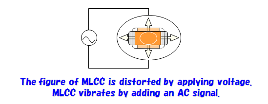
In high dielectric type ceramic capacitors, a dielectric has a slight distortion when the voltage is applied to it. This causes the physical vibration of ceramic capacitors when the volage at audio frequencies is applied to them. The vibration is tranmitted to the board and amplified resulting in a sound from ceramic capacitors.
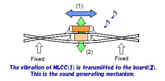
The magnitude of the sound depends on not only the material of a dielectric but also the figure of the capacitor, the size of the board and the mounting state of components. Therefore, you need to take steps from both board layout and parts selection. Please ask our company in detail.
For this type of application, we are preparing Low Distortion High Value Multilayer Ceramic Capacitors(CF_LD)、LW Reversal Decoupling Capacitors (LWDC™) and like that. Please try to use them.
How can I estimate the life of ceramic capacitors?
Considering the life of ceramic capacitors(*1), the applied voltage and the ambient temperature greatly affect to it in general. The following equation(*2) expressed by the applied voltage and the temperature is usually used to estimate the life. After determining the acceleration factor by the acceleration test at an arbitrary temperature and voltage, the life can be estimated by putting your volage and temperature condition into the formula.(*3)
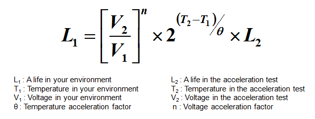
The temperature acceleration factor(θ) and the voltage acceleration factor(n) described here are determined experimentally and different in each product. For example, when the product with the temperature acceleration factor 8 and voltage acceleration factor 4 has a 1000 hour(L2) life in the acceleration test at 20V(V2) and 85℃(T2), the life(L1) at 8V(V1) and 45℃(T1) is roughly estimated as follows by using this formula.
![[8/20]⁴×2(⁸⁵-⁴⁵)/⁸ × 1000 = 1250000 [時間]≃142.69[年]](/en/product/support/useful/faq/mlcc/images/faq_q020_02.png)
-
*1A life end is judged generally based on the degradation of the insulation resistance.
-
*2Because of a simple equation, the life of each product cannot be calculated accurately.
-
*3The life of each product calculated with this formula is not guaranteed. Please ask us a concrete life of each product.
What is MSL?
MSL is JEDEC regulation. This regulation is established to prevent products such
as semiconductors from being damaged resulting from volume expansion by moisture
evaporation at reflow etc. Moisture is mainly absorbed by resin used to seal the
package of semiconductors etc. There is Moisture Sensitivity Level corresponding
to the risk of damage in the regulation. It is needed to take measures
corresponding to the level to pack with a desiccant and perform baking treatment
after a certain period of time passes since unsealed etc.
Because the damage by moisture absorption is mainly caused by resin used in
electronic parts, ceramic capacitors are out of this regulation since they are
resin-less.
What points should I care for using ceramic capacitors?
Precautions on the use of Multilayer Ceramic Capacitors are summarized in catalogs. Please click the link for the product that you are interested in.
Multilayer Ceramic Capacitors
- General Electronic Equipment
- Automotive Electronic Equipment(POWERTRAIN, SAFETY)
- Automotive Electronic Equipment (BODY & CHASSIS, INFOTAINMENT)
- Telecommunications Infrastructure and Industrial Equipment
- Medical Devices classified as GHTF Classes A or B (Japan Classes Ⅰ or Ⅱ)
- Medical Devices classified as GHTF Class C (Japan Class Ⅲ)
-
*A catalog download page for each product is here.
What conditions cause breakdown?
Breakdown is the phenomenon that a dielectric in the insulation layer is destroyed and results in short.
Following 3 cases are considered for the situation of breakdown.
-
1.A product is used under the condition where the voltage, temperature etc. are out of guaranteed range.
-
2.The crack is generated in a product by the mechanical stress.
-
3.The performance of a product degrades since it is used for a long time.
Please use our products under the condition within the guaranteed range according to precautions on the use to prevent such situations.
What points should I care for storing ceramic capacitors?
Please refer to the following extract from precautions on the use in the catalog.
Precautions
- Storage
-
-
1.To maintain the solderability of terminal electrodes and to keep packaging materials in good condition, care must be taken to control temperature and humidity in the storage area. Humidity should especially be kept as low as possible.
Recommended conditions-
Ambient temperature : Below 30℃
-
Humidity : Below 70% RH
The ambient temperature must be kept below 40℃. Even under ideal storage conditions, solderability of capacitor is deteriorated as time passes, so capacitors shall be used within 6 months from the time of delivery. Ceramic chip capacitors shall be kept where no chlorine or sulfur exists in the air.
-
-
2.The capacitance values of high dielectric constant capacitors will gradually decrease with the passage of time, so care shall be taken to design circuits . Even if capacitance value decreases as time passes, it will get back to the initial value by a heat treatment at 150℃ for 1hour.
-
Technical considerations
- Storage
- If capacitors are stored in a high temperature and humidity environment, it might rapidly cause poor solderability due to terminal oxidation and quality loss of taping/packaging materials. For this reason, capacitors shall be used within 6 months from the time of delivery. If exceeding the above period, please check solderability before using the capacitors.
-
*cPrecautions on the use is here.
Are Taiyo Yuden ceramic capaictors compliant with EU RoHS Directive and REACH Regulation?
All of ceramic capacitors listed on our catalogs are compliant with Rohs New Directive (2011/65/EU) published in 2011 and REACH Regulation (EC 1907/2006) effective from 2007. Also, they are compliant with applicable environment regulations of law in force in major countries such as U.S.A., china and so on.
About products listed on catalogs that are sold directly from
us, we are applying a management system in order to be compliant with above
regulations from the purchase of materials to production and sales. About our
products that trading and agent companies are dealing with, please ask
them.
Please ask the nearest sales office about each product. Please agree in
advance that we cannot answer details to inquiries about product compliance
posted to inquiry form on our home page from the point of view of information
security.
Please see this page about our environmental activities.
Please tell me the meaning of MΩ•μF as an unit of insulation resistance.
MΩ•μF is the product of insulation resistance and capacitance. For example, in case that the specification of insulation resistance for a 0.1μF capacitor is 500MΩ•μF, the insulation resistance value is 500MΩ•μF / 0.1μF = 5000MΩ.
What is the status of the ISO certification?
Please refer to this section for the status of the ISO certification acquisition.
Is it possible to ask you to confirm whether the ceramic capacitors I purchased were counterfeit?
For more information on counterfeit products, please see here.
Please let me know the results of the determination of whether ceramic capacitors are subject to the Foreign Exchange and Foreign Trade Control Law and the U.S. Export Administration Regulations (EAR). Also, please provide us with a written report of such compliance/non-conformity.
Please contact us here for the non-judgment.
Mounting
Are there any precautions that need to be checked before mounting a multilayer ceramic capacitor?
Please refer to this section for precautions to be taken before mounting multilayer ceramic capacitors.
Please tell me soldering conditions and matters to be cared
for soldering.
What is a suitable amount for soldering?
Soldering conditions are summarized at precautions on the use in catalogs. Click the link of the product that you are interested in.
Multilayer Ceramic Capacitors
- General Electronic Equipment
- Automotive Electronic Equipment(POWERTRAIN, SAFETY)
- Automotive Electronic Equipment (BODY & CHASSIS, INFOTAINMENT)
- Telecommunications Infrastructure and Industrial Equipment
- Medical Devices classified as GHTF Classes A or B (Japan Classes Ⅰ or Ⅱ)
- Medical Devices classified as GHTF Class C (Japan Class Ⅲ)
-
*A catalog download page for each product is here.
Are there any precautions regarding flux application for multilayer ceramic capacitors?
In the catalog, there is a summary of precautions regarding flux application. Please click on the link of the product you wish to view.
Multilayer Ceramic Capacitors
- General Electronic Equipment for Consumer
- Automotive Electronic Equipment(POWERTRAIN, SAFETY)
- Automotive Electronic Equipment (BODY & CHASSIS, INFOTAINMENT)
- Telecommunications Infrastructure and Industrial Equipment
- Medical Devices classified as GHTF Classes A or B (Japan Classes Ⅰ or Ⅱ)
- Medical Devices classified as GHTF Class C (Japan Class Ⅲ)
-
*A catalog download page for each product is here.
Are there any precautions for flow soldering?
The catalog summarizes precautions regarding flow soldering.
Please click on the link for the product you wish to view.
Multilayer Ceramic Capacitors
- General Electronic Equipment for Consumer
- Automotive Electronic Equipment(POWERTRAIN, SAFETY)
- Automotive Electronic Equipment (BODY & CHASSIS, INFOTAINMENT)
- Telecommunications Infrastructure and Industrial Equipment
- Medical Devices classified as GHTF Classes A or B (Japan Classes Ⅰ or Ⅱ)
- Medical Devices classified as GHTF Class C (Japan Class Ⅲ)
Are there any points to be noted when dividing the substrate after mounting the multilayer ceramic capacitor?
The catalog contains a summary of precautions for board separation operations.
Please click on the link for the product you wish to view.
Multilayer Ceramic Capacitors
- General Electronic Equipment
- Automotive Electronic Equipment(POWERTRAIN, SAFETY)
- Automotive Electronic Equipment (BODY & CHASSIS, INFOTAINMENT)
- Telecommunications Infrastructure and Industrial Equipment
- Medical Devices classified as GHTF Classes A or B (Japan Classes Ⅰ or Ⅱ)
- Medical Devices classified as GHTF Class C (Japan Class Ⅲ)
-
*A catalog download page for each product is here.
Please tell me recommended land dimensions.
Land dimensions are summarized at precautions on the use in catalogs.
Please click the link of the product that you are interested in.
Multilayer Ceramic Capacitors
- General Electronic Equipment
- Automotive Electronic Equipment(POWERTRAIN, SAFETY)
- Automotive Electronic Equipment (BODY & CHASSIS, INFOTAINMENT)
- Telecommunications Infrastructure and Industrial Equipment
- Medical Devices classified as GHTF Classes A or B (Japan Classes Ⅰ or Ⅱ)
- Medical Devices classified as GHTF Class C (Japan Class Ⅲ)
-
*A catalog download page for each product is here.
Data
Where can I download S-parameter and SPICE model of ceramic capacitors?
Where can I download a catalog of ceramic capacitors?
Catalogs are provided at Product information in PDF/S Parameter/SPICE model.
Where can I download the characteristic data sheet for ceramic capacitors?
For data not shown in the frequency response graph, please contact us here.
Where can I download a characteristic datasheet of ceramic capacitors?
After searching each product you want to see in TY-COMPAS, you can access the detailed product page from the product link of the result table. You can download the characteristic datasheet from the document section in that page.
Others
Do ceramic capacitors contain conflict minerals?
For information on conflict minerals, please contact us here.
Which countries and factories were the ceramic capacitors produced in?
Please refer to this section for the countries and factories where ceramic capacitors are produced.