Product Search
- Distributor Inventory Search
- North America
- Europe
- Asia Pacific
- Other Regions
- Product & Solution Lineup
- Special Contents
- Design Support Tools
- Helpful Tips
- Product Information News
Product & Solution Lineup
Product
-
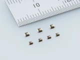
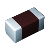
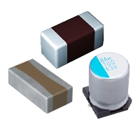
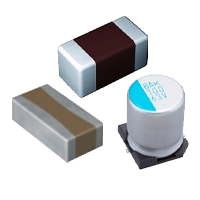
Multilayer Ceramic Capacitors
-
Multilayer Ceramic Capacitors The demand of multilayer ceramic capacitors with over 100μF capacitance is increasing for industrial devices such as communication infrastructures, etc.
-
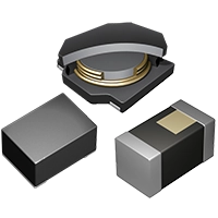
Inductors
-
Contributing to achieve even lower power consumption of high-performance and multi-functional smartphones and such small and low-profile digital devices.
-
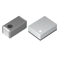
RF Devices
-
Supports a wide range of needs with the existing three technologies of multilayer ceramic, FBAR and SAW
-
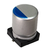
Conductive Polymer Hybrid Aluminum Electrolytic Capacitors
-
Best-suited for onboard equipment and industrial machinery that require high capacities and high voltage resistance.
Solutions
-
High Reliability Products (for Automotives)
-
Responding to market needs by supplying high-reliability products with optimum materials and designs.
-
High Reliability Products (for Industrial Equipment)
-
Responding to market needs by supplying high-reliability products with optimum materials and designs.
-
Multilayer Piezoelectric Actuators

-
The Multilayer Piezoelectric Actuators provide not only oscillations, but delicate and high-quality tactile sensations based on piezoelectric element technologies. This enables applications in touch devices through tactile functions.
-
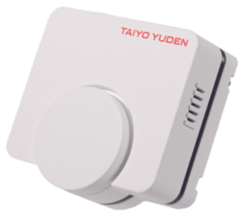
Smell Sensors
-
Can we see smells?
Technology for visualizing smells is under development!
Smell analysis technology accelerated by AI
-
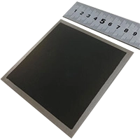
Metal Supported - Solid Oxide Fuel Cell(MS-SOFC)
-
Metal-Supported Solid Oxide Fuel Cell (MS-SOFC) with excellent handling and power generation characteristics.
-
Regenerative Electric Assist System FEREMO™

-
Safe and secure new mobility for the people and environment
Special Contents
"Learn with Manga! Meet 'FEREMO™' — It Charges, Generates, and Supplies Power!"

Regenerative Electric Assist System FEREMO™
Regenerative Electric Assist System FEREMO™
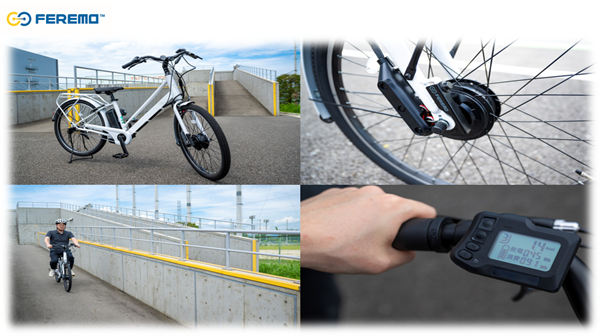
Capable of traveling up to 1000 km on a single charge
[Roundtable Discussion] TAIYO YUDEN (FEREMO™) × Maruishi Cycle (Re:BIKE)
The ideal future of bicycles as a part of daily life.
Regenerative Electric Assist System FEREMO™

Long-distance travel without worrying about battery charging!
Introducing the groundbreaking system 'FEREMO™' that supports electric assist bicycles.
Design Support Tools
TY-COMPAS
Search TAIYO YUDEN products by features and specifications.

Product Information in PDF
S-Parameter
SPICE model
TAIYO YUDEN Product Information in PDF / S-Parameter / SPICE model are available.

Power Inductor Selection WEB
For selecting the most suitable power inductor for DCDC converters.

Easy PDN Tool (TY-PDN Tool)
Easy-calculation tool for combined impedance of capacitors in PDN (Power Distribution Network).

Simulator for EMC Components
TAIYO YUDEN original software for choosing optimum EMC countermeasure components is available on this page.

Component Library
Component Library for your circuit/SI/PI simulators is available on this page.

Helpful Tips
Download Documents
White papers and the documents provided in exhibitions are available.

Video Library
Learn about TAIYO YUDEN products from videos.

The Fundamental Technical Knowledge
Introducing basic knowledge about capacitors

Q&A Corner
Frequently Asked Questions about capacitors and inductors

Event Information
Information on events and exhibitions

Product Information News
-
Product & Solution

-
Product & SolutionChanges to the Part NumbersProduct
-
Product & Solution